| |
Character Rigging In Maya
Introduction
Hello, this is a
tutorial to introduce people to the sometimes complicated
world of character rigging. As with all my tutorials, I
intend to take you through this with as much help and
explanation of the techniques as I can.
Hopefully, at the end
of this tutorial, we'll all have a completed rig for a biped
character and a better understanding of the whole process in
general, albeit aimed at beginners, I intend to get quite in
depth later on, although like I said before, I will be
explaining everything I can as I go along to help the
understanding of why and what is going on in each
section.
In most cases, these
tutorials I create start out as being a collection of notes
and findings of my own research, which, in turn, just so
'I' can understand the processes become easy to read
notes, and then develop into my own tutorial on the subject
matter, in this case, character rigging. I will also
delve a little into blend shapes, and also how to set up
low-poly 'stand in' object for animating with, and how to
export and import animation from the low-res version to the
high-res version.
As in other tutorials
of this kind, where you get pages and pages of instruction
which is sometimes a little hard to understand and follow, I
don't want to do that, instead, what I'm going to do is
actually provide a model of one of my characters for you to
work with and follow along properly with this tutorial, this
means that you will be getting 'real world' experience as you
progress and hopefully learn what you need to, to set up your
own rigs and so on.
Ok, before we move
onto the main part of the tutorial, I firstly want to
introduce some basic information that will aid us later on in
this tutorial, forgive me if it comes across a little basic
right now, but I've aimed this at beginners to start
with. Hope you all follow along and enjoy this learning
process! :)
Basic
Information
Ok, this section is just to
introduce some fairly basic terms before we move on into the
main rigging tutorials, provided only as a basic heads up for
beginners, who may or may not know these terms and
explanations.
IK (Inverse Kinematics)
and FK (Forward Kinematics)
Forward Kinematics
(FK)
Forwards Kinematics or FK as
it is more widely known is a way of posing or animating a
skeleton each part / bone at a time, for example, in the case
of an arm using FK, to animate it reaching forward, you would
need to rotate the arm at the shoulder joint, and then you
would need to rotate the joint directly below that at the
elbow. It is quite an intuitive way to animate as it
provides a good visual way of posing the character just by
rotating the joints into position.
Inverse Kinematics
(IK)
Inverse Kinematics or IK as
it is more widely known is a way of posing or animating a
skeleton by using a goal based system, IK, in my opinion would
be best described as imagine you have no control of you own
arm, and someone else instead moves it for you, the easiest
way for this person to move you arm into the required position
would be to grab your arm at the wrist and then move it into
position, the whole rest of the arm would follow accordingly,
this is how IK works. In the case of an arm, you would
have shoulder and forearms joints, you would then create an IK
chain from the top to the bottom, and then when you have done
that, you would select the IK handle that would be created at
the bottom of the forearm joint (wrist area) and the just move
that, the whole arm would then move along accordingly.
Maya provides three
different types of IK Solver, these are (default) ikRPSolver
(Rotate Plane), ikSCSolver (Single Chain) and also the IK
Spline Handle. These are in turn described as :
-
ikRPSolver
The Rotate Plane IK Solver
is the default IK Solver and is probably used the most when
setting up characters, it is most useful when used in
conjunction with chains in joints such as an arm (where
the elbow will need to be rotated into place) or a leg (where
the knee will need to be rotated into place). It
essentially has the ability to control the twisting direction
of the chain that it is controlling.
ikSCSolver
The Single Chain IK Solver
is used when no twisting action is required of the joint
chain, as in a characters foot for example.
IK Spline
Handle
The IK Spline Handle is
actually quite a powerful handle, it is best used when you
would have a complex series of joints, for example a
characters spine or a character who has a tail, in both cases
you would require a solver that would simplify the process of
animating a lot of joints together in the same area at the
same time. When a Spline Handle is used between a chain
of joints, a Spline is created along the chain, and in turn
the CV's (Control Vertices) are what would be selected and
manipulated for animating with, generally the CV's would in
turn be constrained to Cluster Deformers for ease of use when
manipulating for animation.
Constraints
As the Maya Online
Help states 'Constraints enable you to constrain the position,
orientation, or scale of an object to other objects. Further,
with constraints you can impose specific limits on objects and
automate animation processes.' Constraints are used
quite a lot in animation and character setup, and it's
worthwhile getting to know how they all work, so you can best
utilise them within your scenes. Maya offers a number of
different types of constraints, these are : -
Point constraints -
Point constraints constrain an object's position to the
position of one or more objects. For example,
constraining a button to a characters shirt.
Aim
constraints - Aim constraints constrain an object's
orientation so that it always aims at other objects. For
example, constraining eyes on a character so that they always
look in a particular direction.
Orient
constraints - An orient constraint causes an object to
follow the orientation of one or more objects. For example, a
crowd scene may require all characters to look in a particular
direction at the same time, you can orient constrain all the
heads to one main character to set this up.
Scale
constraints - A scale constraint causes an object to
follow the scaling of one or more objects. For example,
constraining two characters together so that when grows (scale
Y), the other grows too.
Geometry constraints -
A geometry constraint restricts an object to a NURBS surface,
NURBS curve, or polygonal surface (mesh). For example,
constraining a drinks can to a characters
hand.
Normal constraints - Normal constraints
constrain an object's orientation so that it aligns with the
normal vectors of a NURBS or polygonal surface (mesh).
For example, constraining a spider to a character to get it to
walk over the surface correctly.
Tangent
constraints - Tangent constraints constrain an object's
orientation so that the object always points in the direction
a curve. For example constraining a fly character to a curve
so that it animates along the curve and keeps the direction
that the curves holds, i.e. if it goes up, the fly character
would be facing up.
Pole vector constraints
- A pole vector constraint constrains an IK rotate plane
handle's pole vector. For example,. controlling the
position of a characters knee of elbow when animating (more
information later).
Ok, we're done with
the basics, I hope I haven't bored you too much yet, now we
should be ready to move onto the main meat of the tutorial,
but before we carry on, if your wanting to follow along
completely so that you understand fully what your doing,
download this model I have created which we will
rig together as we progress : -
NOTE
NOT ALL DOWNLOADS ARE
AVAILABLE PLEASE DOWNLOAD THIS ONE,
AS IT SHOULD CONTAIN THE MOST USED SCENE FILES IN THIS
TUTORIAL
MAIN SCENE FILES DOWNLOAD
Ok, once you've downloaded this
model, extract the contents and open the file up within Maya,
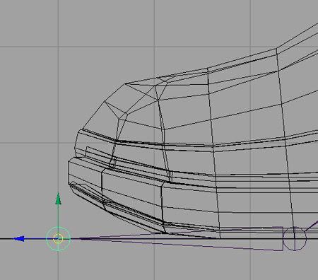
you should have something like this : -
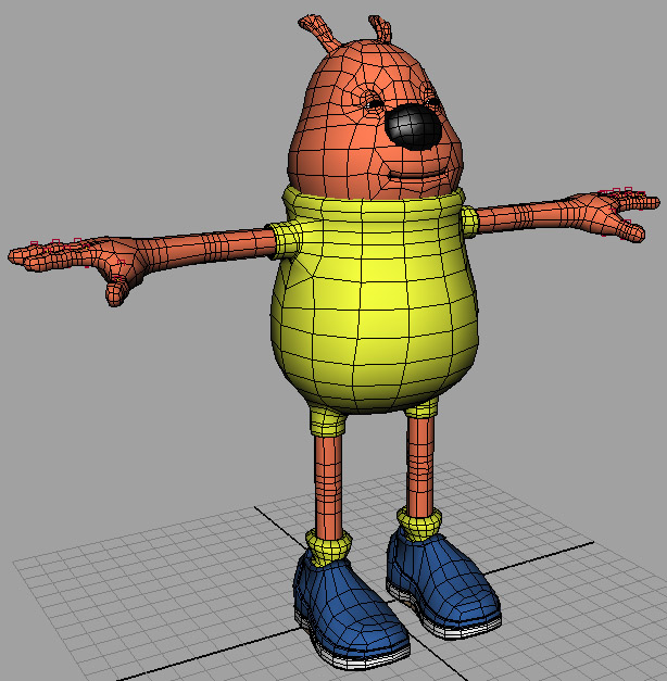
! Note, In This Screengrab, I Have
'Wireframe On Shaded' Switched On !
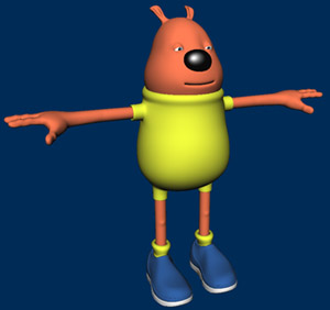
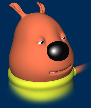
Now, it looks slightly different to
the nice smooth versions posted above, the difference being
this model is the low-polygon version that I normally
build for conversion to either subdivision surfaces or polygon
smoothing. Because it is low-polygon, it will be
much easier to set up and rig due to the low overhead and
uncomplicated layout, as opposed to the polygonally dense mesh
that you would get with a 'smoothed' version. There is
some other notes I need to make about the scene, but I will do
this as we progress on, now onward we go....
Setting Up The Skeleton
In the scene, open up the the
Outliner, Window > Outliner. Within the
outliner, you will see two groups, one called Character
and the other Guide_Curves, The Character group
node contains all of our characters body parts, such as his
head, hands, legs, teeth, gums and so on, I've grouped them
this way just to make the scene cleaner and more manageable
when looking for things, the Guide_Curves group node is a
group containg some Nurbs Curves which I have placed around
the characters body, the 'Guide' curves will aid us in
creating our Skeleton, and will be deleted later on, select
the Guide_Curves group node within the Outliner, and then
maximises your Perspective window and press number 4 to
display the wireframe, you should be able to see the Nurbs
Guide Curves a little better this way, it should resemble this
diagram : -
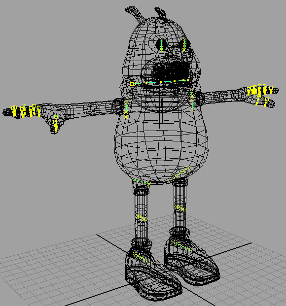
As you can see, I have set up Guide Curves in
some key areas, but not all, this step is not essential, but I
find it helps me when placing my joints, the key areas I have
covered are the centre pivots for the eyes, the head, the
shoulders, each joint area in the fingers, the top of the leg,
the knees and the ankle areas. Let's start setting up
our Skeleton now : -
ok, first things first, create a
new layer and call it Skeleton_L, this will become the layer
where we will store all of our joints. Now that you have
created the extra layer, we will now begin placing
joints. We will begin with the legs, press F2 if you are
not already in animation mode, and then select SKELETON
> JOINT TOOL, in the Layers Menu, set the
Character_L Layer to T for Templated.
Although we have guide curves for both sides of the body,
we're only going to be using one side, and then mirroring our
joints across to the other side, we will be using our
characters right side as your looking at him when setting up
the joints to be mirrored. Now, hopefully you should
still have your Skeleton > Joint Tool still selected, if
not, select it again, and then in your side view, draw the
following joint chain : -
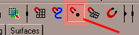
Now, we're going to move the joints into
position, maximise your Perspective view by pressing the Space
Bar quickly whilst holding the mouse over it, now switch on
Snap To Points : -
and then in relation to where your joints are,
snap each joint to the following points on each of the guide
curves, as shown in this diagram : -
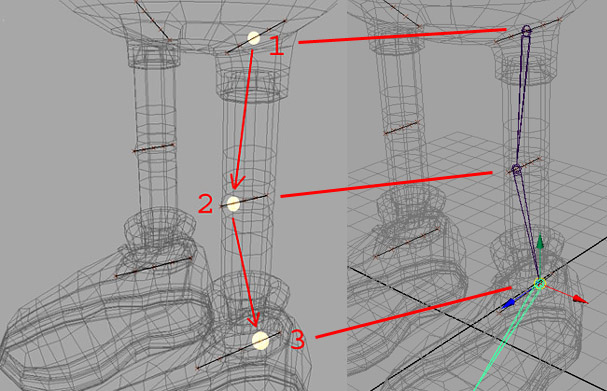
So, essentially, you start from the top of the
leg and work your way down when snapping to the joints, with
the 3 nurbs curves, you should snap in this order, 1st - Snap
to to middle CV of the top curve, at the Knee Area, you should
snap the 2nd Joint to the second CV in from the front of the
knee, and then on the 3rd point your snapping to, make sure it
is the second CV in from the back of the guide curve. In
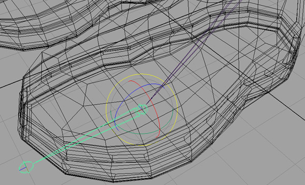
the Layers menu, switch off the V - Visibility for the
Curve_Guides Layer, and in the Charater_L Layer, change it
from a template to an R - Reference Layer, now snap
your next joint to the following Vertex on the sole of
the foot: -
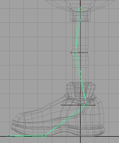
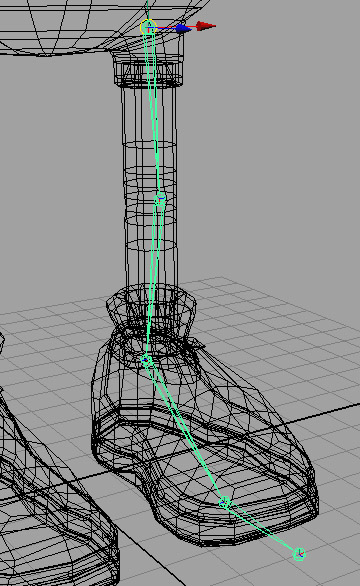
And then one more to finish, switch to your side
view, and change your snapping to grid snapping instead and
then snap to this grid point at the front of the shoe :
-
Once you've snapped the last one, you should now
have a chain of joints for your leg, similar to this diagram :
-
Select the first Joint you created,
joint1, and within the layers menu, right click over
the Skeleton_L Layer and click on Add Selected Objects, if you
haven't already done so, I would also add a colour to the
layer, so you can easily identify what is contained within any
given Layer, I've chosen Blue, as it stands out and is easy to
read. We haven't quite finished just yet though, we will
be adding some more joints when we come to do the reverse foot
setup, but that is later, right now, we're going to rename our
currently created joints, open up the Outliner, and take a
look at your joints, with respect to each one's position,
rename them like this : -
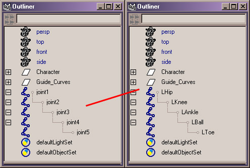
That reads a lot better now, and you now have a
much better idea of what each joints role will be in the
hierarchy. We will now move onto creating the arm
joints, so again in the Layers Menu, set the
Character_L Layer to T for Templated, and set
the Curve_Guides back to V - Visible.
Switch to the front view, as this is where we will be placing
our joints for the arm, and without any snapping turned on,
create the following joints for the arm, don't worry too much
about placement right now, just so long as it roughly matches
this diagram : -
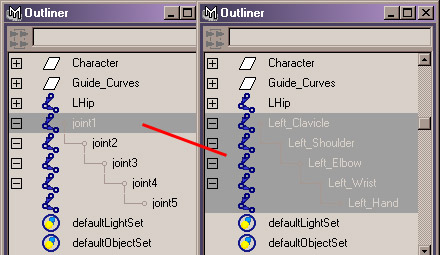
Within your Outliner, rename the joints,
starting from the first one, like this : -
Now, we need to place them properly, maximise
your Persp view, and keep your outliner open, within it,
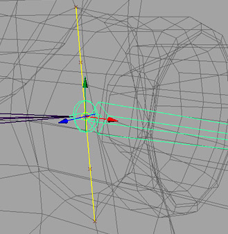
select the Left_Shoulder joint, now, Snap to the Middle
CV on the nurbs curve in that area : -
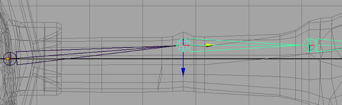
Now, select the Left_Elbow joint, and in
the top view, Do Not Snap, move it into position so it
roughly matches this diagram : -
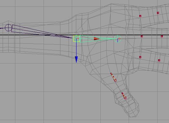
Now, select the Left_Wrist joint,
and again, in the top view, move that joint into position so
it roughly matches this position : -
Now, the last joint will be fine, and so will
not need moving. Within the outliner, select the first
joint, Left_Clavicle and then add it to the
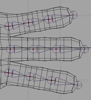
Skeleton_L Layer. Now, let's place the finger
joints, in the top view, using Grid Snapping, create the
following joints, remember to press Enter when you have
created the first lot, don't worry about where there being
placed, as we'll be snapping them into place later :
-
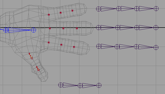
Next, maximise your Persp view, and then switch
off Grid Snapping and instead use Point Snapping, and in turn
snap each joint to it's corresponding Guide Curve, when
snapping to the Guide Curve, snap to the Middle CV on
it. You should end up with something like this :
-
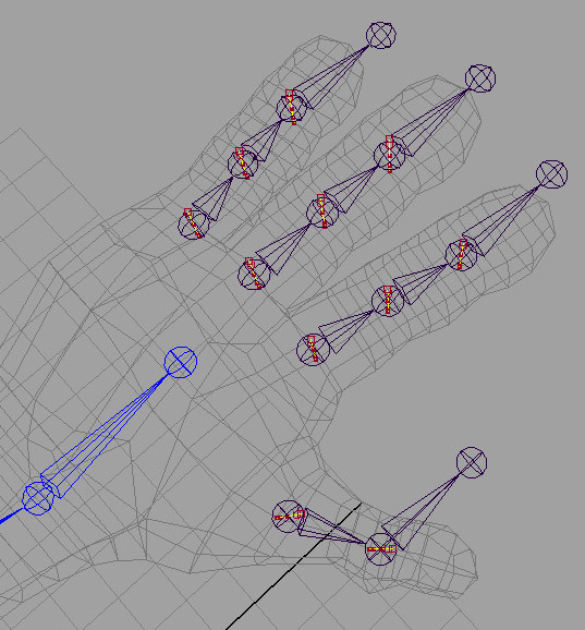
Ok, we're not finished just yet, in your Top
View, select the last joint in turn on each finger joints, and
the Thumb joint, turn your Character_L Layer from
T - Template, to R - Reference, one, and 1 by 1
snap to these points on the end of the actual mesh, see this
diagram : -
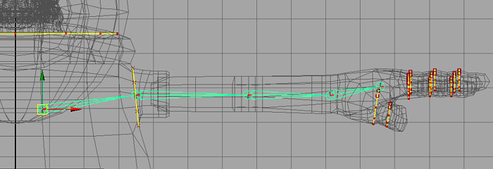
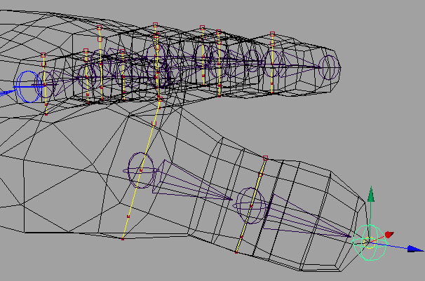
And the last joint in the Thumb Joint hierarchy
(Probably best placed in the Persp View) : -
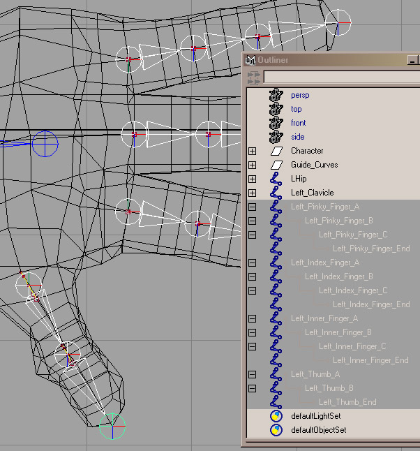
Now name your joints in turn, starting from the
first set you created, I recommend the following naming
convention, Left_Pinky_Finger_etc, Left_Index_Finger_etc,
Left_Inner_Finger_etc, and finally, Left_Thumb_etc, you can
see what I've done here, ( Tip - To save the tedium of
repetitive typing, type the first name, and then select it,
Press CTRL + C to copy it, and then with the next joint, press
CTRL + V to past it in, and then change it to what you need )
: -
And finally, select all the new joints and add
them to the Skeleton_L Layer. You can set the
Character_L Layer back to template now too. Don't
worry about the finger joints not being connected to anything,
we'll sort that part out later. Now we're going to move
onto creating the Spine joints.
Because this
tutorial is quite graphics intensive, I'm going to have to
consider people with slower connections too, so I'm going to
continue the tutorial on a new page : -
Just follow the
link below : -
Character
Rigging Tutorial - Second Page
|
|
